

Ball Joints
Danuser Ball Joints are manufactured for use in a variety of applications. From connecting ends for adjustment links and pitch control links, to cylinder heads and rod ends, Danuser Ball Joints are the answer where a flexible connection is required. This multi-directional movement of the spherical ball prevents binding on clevis ends and other non-spherical connections. Retainers are also available with provisions for grease fittings and grease grooves. The balls are machined smooth and case hardened to minimum Rockwell C-62 for superior wear. The standard Ball finish is plain. Zinc plating of the Ball is available on special orders. Danuser welcomes your inquiries on ball joint assemblies made to your design and specification.
|
Part ID
|
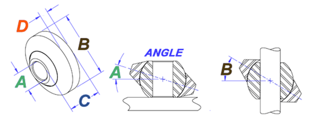
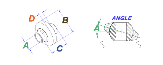
A
Pin Size (in.)
|
B
Retainer OD (in.)
|
C
Ball Width (in.)
|
D
Retainer Width (in.)
|
Angle A (deg.)
|
Angle B (deg.)
|
Ultimate Retainer Strength (lbs.)
|
Ball Push Out Force (lbs.)
|
Image
|
CAD
|
|---|---|---|---|---|---|---|---|---|---|---|
| 5982 |
0.5
|
2
|
1
|
3/8
|
11°
|
40°
|
20,000
|
14,600
|

|

|
| 5870 |
0.62
|
2
|
1
|
3/8
|
11°
|
33°
|
20,000
|
14,600
|

|
|
| 5974 |
0.62
|
2.25
|
1
|
3/8
|
10°
|
35°
|
45,000
|
17,100
|

|
|
| 5868 |
0.75
|
2
|
1
|
3/8
|
11°
|
26°
|
20,000
|
14,600
|

|
|
| 5973 |
0.75
|
2.25
|
1
|
3/8
|
10°
|
28°
|
45,000
|
17,100
|

|
|
| 5347 |
0.75
|
2.25
|
1.38
|
9/16
|
17°
|
30°
|
32,800
|
26,200
|

|
|
| 5860 |
0.75
|
2.5
|
1.38
|
3/8
|
17°
|
32°
|
52,000
|
28,500
|

|
|
| 5088 |
0.87
|
2.25
|
1.38
|
9/16
|
17°
|
27°
|
32,800
|
26,200
|

|
|
| 5827 |
0.87
|
2.5
|
1.38
|
3/8
|
17°
|
26°
|
52,000
|
28,500
|

|
|
| 7466 |
1
|
2
|
1
|
3/8
|
11°
|
17°
|
20,000
|
14,600
|

|
|
| 5975 |
1
|
2.25
|
1
|
3/8
|
10°
|
19°
|
45,000
|
17,100
|

|
|
| 5526 |
1
|
2.75
|
1.75
|
7/8
|
17°
|
26°
|
40,500
|
35,100
|

|
|
| 5849 |
1
|
3.12
|
1.75
|
9/16
|
15°
|
31°
|
78,900
|
46,000
|

|
|
| 5832 |
1.12
|
2.75
|
1.38
|
11/16
|
10°
|
30°
|
35,500
|
35,100
|

|
|
| 5495 |
1.12
|
2.75
|
1.75
|
13/16
|
17°
|
28°
|
40,500
|
35,100
|

|
|
| 5859 |
1.12
|
3.12
|
1.38
|
3/8
|
11°
|
32°
|
50,000
|
23,700
|

|
|
| 5836 |
1.12
|
3.12
|
1.75
|
9/16
|
15°
|
25°
|
78,900
|
46,000
|

|
|
| 5924 |
1.25
|
2.75
|
1.75
|
7/8
|
17°
|
25°
|
40,500
|
35,100
|

|
|
| 5925 |
1.25
|
3.12
|
1.75
|
9/16
|
15°
|
24°
|
78,900
|
35,100
|

|
|
| 5865 |
1.43
|
3.5
|
1.75
|
1/2
|
13°
|
24°
|
82,400
|
40,200
|

|
|
| 5976 |
1.43
|
3.5
|
1.75
|
1/2
|
13°
|
23°
|
82,400
|
40,200
|

|
|
| 5918 |
1.43
|
4
|
1.75
|
5/8
|
13°
|
23°
|
135,000
|
47,900
|

|
|
| 5987 |
1.5
|
4.5
|
2.5
|
1
|
20°
|
33°
|
162,000
|
68,600
|

|
|
| 5910 |
1.75
|
4.5
|
2.5
|
11/16
|
20°
|
28°
|
162,000
|
68,600
|

|
|
| 5912 |
2
|
4.5
|
2.25
|
1
|
14°
|
22°
|
162,000
|
68,600
|

|
|
|
Part ID
|
A
Pin Size (in.)
|
B
Retainer OD (in.)
|
C
Ball Width (in.)
|
D
Retainer Width (in.)
|
Angle A (deg.)
|
Angle B (deg.)
|
Ultimate Retainer Strength (lbs.)
|
Ball Push Out Force (lbs.)
|
Image
|
CAD
|
|---|---|---|---|---|---|---|---|---|---|---|
| 5500 |
0.75
|
2
|
1.75
|
3/8
|
17°
|
0°
|
20,000
|
14,600
|

|
|
| 5988 |
0.75
|
2.25
|
1.75
|
3/8
|
15°
|
0°
|
45,000
|
17,100
|

|
|
| 5985 |
1.25
|
3.5
|
2
|
1/2
|
20°
|
0°
|
82,400
|
40,200
|

|
|
| 5984 |
1.25
|
4
|
2
|
5/8
|
18°
|
0°
|
135,000
|
47,900
|

|
|